What the scanner actually captures
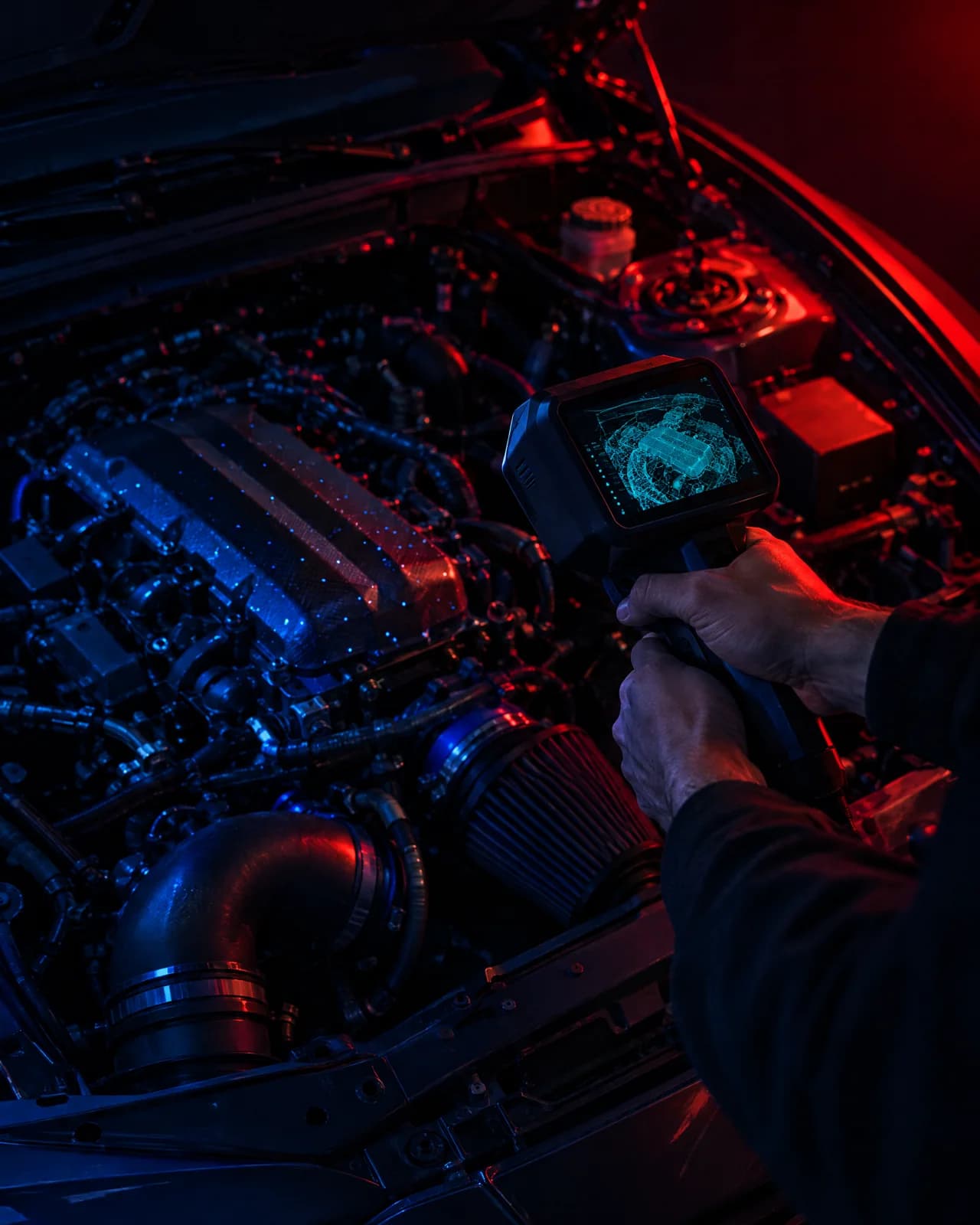
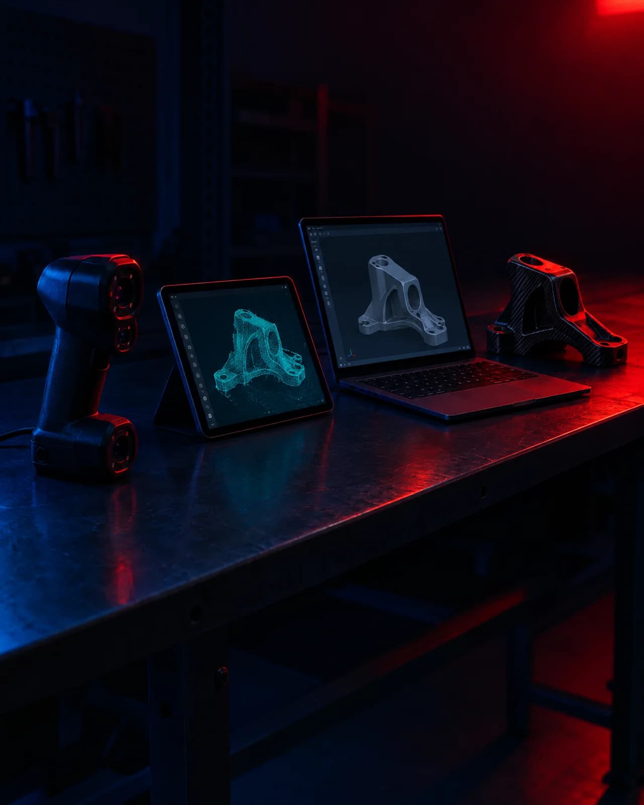
A handheld 3D scanner projects a pattern onto the surface and reads how it deforms, building up a cloud of points and then a mesh — a skin of small triangles that follows the surface. It captures what's there with good accuracy, including wear, damage and the aftermarket parts nobody has a drawing for. It does not capture intent: it doesn't know a hole is meant to be round, or a face is meant to be flat.
Why a mesh isn't a part
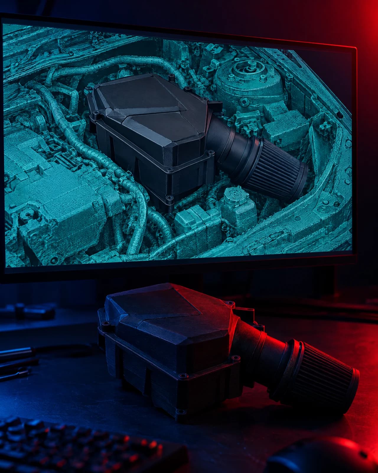
A mesh is heavy, bumpy and un-editable in any useful engineering sense. You can't change a hole diameter, add a boss, or thicken a wall — you can only push triangles around. It also carries the scan's noise: a flat face is thousands of slightly uneven facets. Printing directly from a raw mesh reproduces all of that, which is fine for a rough check and wrong for a finished part.
Scan-to-CAD: rebuilding the geometry
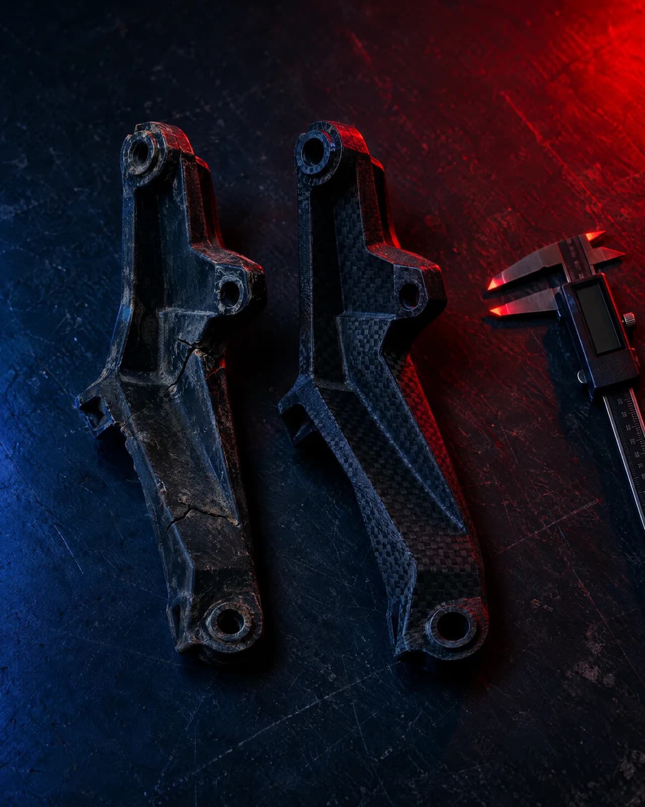
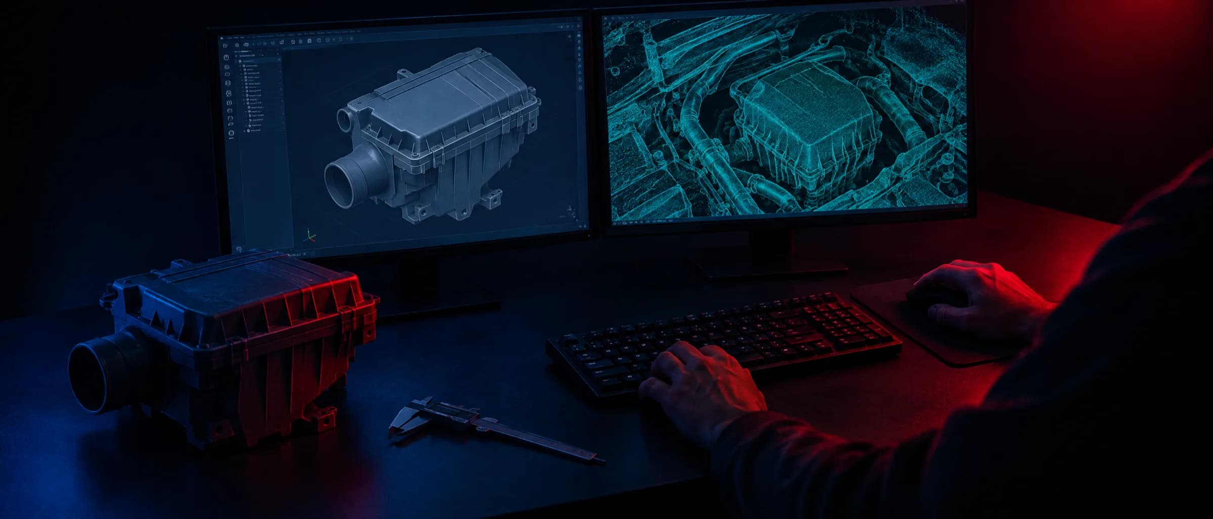
The engineer models the part over the mesh in parametric CAD — real cylinders, real planes, real fillets — using the scan as the reference for where everything sits. That's how a worn bracket becomes a clean bracket with the right hole positions, and how a new airbox is designed to clear a strut tower that the scan says is exactly there. This is the step that takes the time and the skill, and it's what you're paying for.
The difference between a part that clears the strut tower and one that nearly does is the accuracy of the scan and the care in the CAD. Both matter.
Designing for manufacture
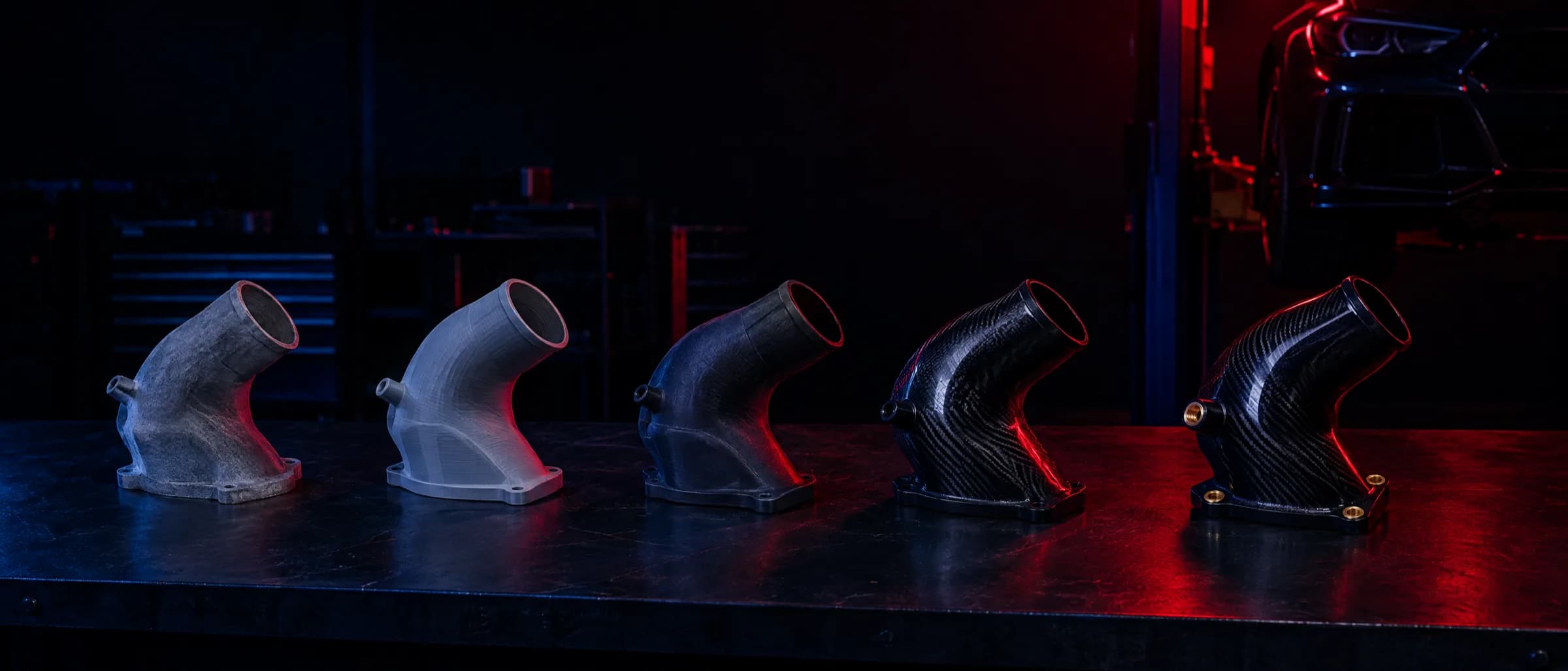
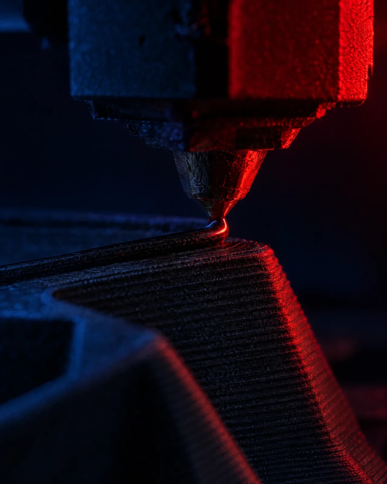
A good scan-to-CAD job doesn't just copy the original — it improves it where the original had a weakness, and it's designed for how it'll be made. Wall thicknesses and orientation for printing; flat patterns for laser cutting; places for heat-set inserts. The file that comes out is ready to make, not just ready to look at.
Prototype, test fit, manufacture
A prototype is printed and fitted to the actual car or assembly. Revisions go back into the CAD. Then the locked file is manufactured — printed here in Brendale, or laser cut and powder coated where it's metal — and it's repeatable from then on. See the services pages for each stage on its own.